Friday, July 13, 2018

TCP Connection Termination

             In TCP 3-way Handshake Process we studied that how connection establish between client and server in Transmission Control Protocol (TCP) using SYN bit segments. In this article we will study about how TCP close connection between Client and Server. Here we will also need to send bit segments to server which FIN bit is set to 1.
11
How mechanism works In TCP :
  1. Step 1 (FIN From Client) – Suppose that the client application decides it wants to close the connection. (Note that the server could also choose to close the connection). This causes the client send a TCP segment with the FIN bit set to 1 to server and to enter the FIN_WAIT_1 state. While in the FIN_WAIT_1 state, the client waits for a TCP segment from the server with an acknowledgment (ACK).
  2. Step 2 (ACK From Server) – When Server received FIN bit segment from Sender (Client), Server Immediately send acknowledgement (ACK) segment to the Sender (Client).
  3. Step 3 (Client waiting) – While in the FIN_WAIT_1 state, the client waits for a TCP segment from the server with an acknowledgment. When it receives this segment, the client enters the FIN_WAIT_2 state. While in the FIN_WAIT_2 state, the client waits for another segment from the server with the FIN bit set to 1.
  4. Step 4 (FIN from Server) – Server sends FIN bit segment to the Sender(Client) after some time when Server send the ACK segment (because of some closing process in the Server).
  5. Step 5 (ACK from Client) – When Client receive FIN bit segment from the Server, the client acknowledges the server’s segment and enters the TIME_WAIT state. The TIME_WAITstate lets the client resend the final acknowledgment in case the ACK is lost.The time spent by client in the TIME_WAIT state is depend on their implementation, but their typical values are 30 seconds, 1 minute, and 2 minutes. After the wait, the connection formally closes and all resources on the client side (including port numbers and buffer data) are released.
In the below Figures illustrates the series of states visited by the server-side and also Client-side, assuming the client begins connection tear-down.In these two state-transition figures, we have only shown how a TCP connection is normally established and shut-down.
TCP states visited by ClientSide –
TCP states visited by ServerSide –
Here we have not described what happens in certain scenarios like when both sides of a connection want to initiate or shut down at the same time. If you are interested in learning about more this and other advanced issues concerning TCP, you are encouraged to see Stevens’comprehensive book.

TCP Congestion Control

             TCP uses a congestion window and a congestion policy that avoid congestion.Previously, we assumed that only receiver can dictate the sender’s window size. We ignored another entity here, the network. If the network cannot deliver the data as fast as it is created by the sender, it must tell the sender to slow down. In other words, in addition to the receiver, the network is a second entity that determines the size of the sender’s window.
Congestion policy in TCP –
  1. Slow Start Phase: starts slowly increment is exponential to threshold
  2. Congestion Avoidance Phase: After reaching the threshold increment is by 1
  3. Congestion Detection Phase: Sender goes back to Slow start phase or Congestion avoidance phase.
Slow Start Phase : exponential increment – In this phase after every RTT the congestion window size increments exponentially.
Initially cwnd = 1
After 1 RTT, cwnd = 2^(1) = 2
2 RTT, cwnd = 2^(2) = 4
3 RTT, cwnd = 2^(3) = 8
Congestion Avoidance Phase : additive increment – This phase starts after the threshold value also denoted as ssthresh. The size of cwnd(congestion window) increases additive. After each RTT cwnd = cwnd + 1.
Initially cwnd = i
After 1 RTT, cwnd = i+1
2 RTT, cwnd = i+2
3 RTT, cwnd = i+3
Congestion Detection Phase : multiplicative decrement – If congestion occurs, the congestion window size is decreased. The only way a sender can guess that congestion has occurred is the need to retransmit a segment. Retransmission is needed to recover a missing packet which is assumed to have been dropped by a router due to congestion. Retransmission can occur in one of two cases: when the RTO timer times out or when three duplicate ACKs are received.

  • Case 1 : Retransmission due to Timeout – In this case congestion possibility is high.
    (a) ssthresh is reduced to half of the current window size.
    (b) set cwnd = 1
    (c) start with slow start phase again.
  • Case 2 : Retransmission due to 3 Acknowledgement Duplicates – In this case congestion possibility is less.
    (a) ssthresh value reduces to half of the current window size.
    (b) set cwnd= ssthresh
    (c) start with congestion avoidance phase
  • Example – Assume a TCP protocol experiencing the behavior of slow start. At 5th transmission round with a threshold (ssthresh) value of 32 goes into congestion avoidance phase and continues till 10th transmission. At 10th transmission round, 3 duplicate ACKs are received by the receiver and enter into additive increase mode. Timeout occurs at 16th transmission round. Plot the transmission round (time) vs congestion window size of TCP segments.

Internet Protocol version 6 (IPv6) Header

            IP version 6 is the new version of Internet Protocol, which is way better than IP version 4 in terms of complexity and efficiency. Let’s look at the header of IP version 6 and understand how it is different from IPv4 header.
IP version 6 Header Format :
Version (4-bits) : Indicates version of Internet Protocol which contains bit sequence 0110.
Traffic Class (8-bits) : The Traffic Class field indicates class or priority of IPv6 packet which is similar to Service Field in IPv4 packet. It helps routers to handle the traffic based on priority of the packet. If congestion occurs on router then packets with least priority will be discarded.
As of now only 4-bits are being used (and remaining bits are under research), in which 0 to 7 are assigned to Congestion controlled traffic and 8 to 15 are assigned to Uncontrolled traffic.

Priority assignment of Congestion controlled traffic :
Uncontrolled data traffic is mainly used for Audio/Video data. So we give higher priority to Uncontrolled data traffic.
Source node is allowed to set the priorities but on the way routers can change it. Therefore, destination should not expect same priority which was set by source node.
Flow Label (20-bits) : Flow Label field is used by source to label the packets belonging to the same flow in order to request special handling by intermediate IPv6 routers, such as non-default quality of service or real time service. In order to distinguish the flow, intermediate router can use source address, destination address and flow label of the packets. Between a source and destination multiple flows may exist because many processes might be running at the same time. Routers or Host that do not support the functionality of flow label field and for default router handling, flow label field is set to 0. While setting up the flow label, source is also supposed to specify the lifetime of flow.
Payload Length (16-bits) : It is a 16-bit (unsigned integer) field, indicates total size of the payload which tells routers about amount of information a particular packet contains in its payload. Payload Length field includes extension headers(if any) and upper layer packet. In case length of payload is greater than 65,535 bytes (payload up to 65,535 bytes can be indicated with 16-bits), then the payload length field will be set to 0 and jumbo payload option is used in the Hop-by-Hop options extension header.
Next Header (8-bits) : Next Header indicates type of extension header(if present) immediately following the IPv6 header. Whereas In some cases it indicates the protocols contained within upper-layer packet, such as TCP, UDP.
Hop Limit (8-bits) : Hop Limit field is same as TTL in IPv4 packets. It indicates the maximum number of intermediate nodes IPv6 packet is allowed to travel. Its value gets decremented by one, by each node that forwards the packet and packet is discarded if value decrements to 0. This is used to discard the packets that are stuck in infinite loop because of some routing error.
Source Address (128-bits) : Source Address is 128-bit IPv6 address of the original source of the packet.
Destination Address (128-bits) : Destination Address field indicates the IPv6 address of the final destination(in most cases). All the intermediate nodes can use this information in order to correctly route the packet.
Extension Headers : In order to rectify the limitations of IPv4 Option Field, Extension Headers are introduced in IPversion 6. The extension header mechanism is very important part of the IPv6 architecture. Next Header field of IPv6 fixed header points to the first Extension Header and this first extension header points to the second extension header and so on.
IPv6 packet may contain zero, one or more extension headers but these should be present in their recommended order:
Rule : Hop-by-Hop option header(if present) should always be placed after IPv6 base header.
Conventions :
  1. Any extension header can appear at most once except Destination Header because Destination Header is present two times in above list itself.
  2. If Destination Header is present before Routing Header then it will be examined by all intermediate nodes specified in routing header.
  3. If Destination Header is present just above Upper layer then it will be examined only by Destination node.
Given order in which all extension header should be chained in IPv6 packet and working of each extension header :

Introduction and IPv4 Datagram Header

            Network layer is the third layer (from bottom) in the OSI Model.
Responsibilities of Network Layer:
Packet forwarding/Routing of packets: Relaying of data packets from one network segment to another by nodes in a computer network
Connectionless communication(IP): A data transmission method used in packet switched networks in which each data unit is separately addressed and routed based on information carried by it
Fragmentation of data packets: Splitting of data packets that are too large to be transmitted on the network

There are two types of network transmission techniques, circuit switched network and packet switched network.
Circuit Switch vs Packet Switch
In circuit switched network, a single path is designated for transmission of all the data packets. Whereas, in case of a packet switched network, each packet may be sent through a different path to reach the destination.
In a circuit switched network, the data packets are received in order whereas in a packet switched network, the data packets may be received out of order.
IPv4:
IPv4 is a connectionless protocol used for packet switched networks. It operates on best effort delivery model, in which neither delivery is guaranteed, nor proper sequencing or avoidance of duplicate delivery is assured.
IPv4 uses 32-bit (4 byte) addressing, which gives 232 addresses. IPv4 addresses are written in the dot decimal notation, which comprises of four octets of the address expressed individually in decimal and separated by periods, for instance, 192.168.1.5.


IPv4 Datagram Header
Size of the header is 20 to 60 bytes.
VER: Version of the IP protocol (4 bits), which is 4 for IPv4
HLEN: IP header length (4 bits), which is the number of 32 bit
words in the header. Minimum value for this field is 5
and the maximum is 15
Type of service: Low Delay, High Throughput, Reliability (8 bits)
Total Length: Length of header + Data (16 bits), which has a
minimum value 20 bytes and maximum is 65,535 bytes
Identification: Unique Packet Id for identifying the group of
fragments of a single IP datagram (16 bits)
Flags: 3 flags of 1 bit each : reserved bit (must be zero),
do not fragment flag, more fragments flag (same order)
Fragment Offset: Specified in terms of number of 8 bytes, which has
the maximum value of 65,528 bytes
Time to live: Datagram’s lifetime (8 bits), It prevents the datagram
to loop in the network
Protocol: Name of the protocol to which the data is to be passed
(8 bits)
Header Checksum: 16 bits header checksum for checking errors in the
datagram header
Source IP address: 32 bits IP address of the sender
Destination IP address: 32 bits IP address of the receiver
Option: Optional information such as source route.
Due to the presence of options, the size of the datagram header can be of variable length (20 bytes to 60 bytes).

Internet Control Message Protocol (ICMP)

              Since IP does not have a inbuilt mechanism for sending error and control messages. It depends on Internet Control Message Protocol(ICMP) to provide an error control. It is used for reporting errors and management queries. It is a supporting protocol and used by networks devices like routers for sending the error messages and operations information.
e.g. the requested service is not available or that a host or router could not be reached.

Source quench message :

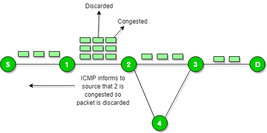
          Source quench message is request to decrease traffic rate for messages sending to the host(destination). Or we can say, when receiving host detects that rate of sending packets (traffic rate) to it is too fast it sends the source quench message to the source to slow the pace down so that no packet can be lost.
ICMP will take source IP from the discarded packet and informs to source by sending source quench message.
Then source will reduce the speed of transmission so that router will free for congestion.


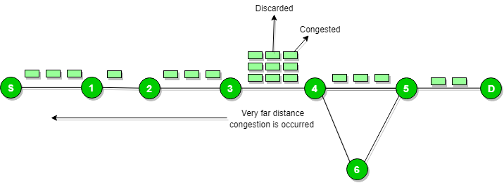
           When the congestion router is far away from the source the ICMP will send hop by hop source quench message so that every router will reduce the speed of transmission.

Parameter problem :

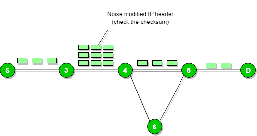
           Whenever packets come to the router then calculated header checksum should be equal to recieved header checksum then only packet is accepted by the router.
If there is mismatch packet will be dropped by the router.
         ICMP will take the source IP from the discarded packet and informs to source by sending parameter problem message.

Time exceeded message :

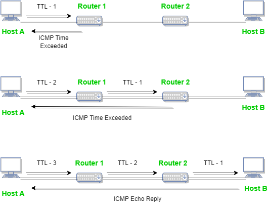
           When some fragments are lost in a network then the holding fragment by the router will be droped then ICMP will take source IP from discarded packet and informs to the source, of discarded datagram due to time to live field reaches to zero, by sending time exceeded message.

Destination un-reachable :

Destination unreachable is generated by the host or its inbound gateway to inform the client that the destination is unreachable for some reason.
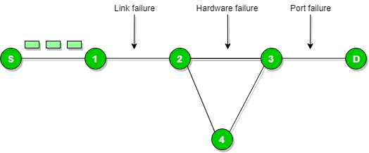
                There is no necessary condition that only router give the ICMP error message some time destination host send ICMP error message when any type of failure (link failure,hardware failure,port failure etc) happen in the network.

Redirection message :

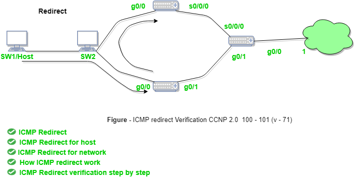
             Redirect requests data packets be sent on an alternate route. The message informs to a host to update its routing information (to send packets on an alternate route).
Ex. If host tries to send data through a router R1 and R1 sends data on a router R2 and there is a direct way from host to R2. Then R1 will send a redirect message to inform the host that there is a best way to the destination directly through R2 available. The host then sends data packets for the destination directly to R2.
The router R2 will send the original datagram to the intended destination.
But if datagram contains routing information then this message will not be sent even if a better route is available as redirects should only be sent by gateways and should not be sent by Internet hosts.
Whenever a packet is forwarded in a wrong direction later it is re-directed in a current direction then ICMP will send re-directed message.

Thursday, July 12, 2018

Onion Routing

             Onion routing is a technique for anonymous communication over a computer network. In an onion network, messages are encapsulated in layers of encryption, analogous to layers of an onion.
           There is a large set of precautionary measures and best practices to make web browsing safer and more secure for users. Let’s say that you send an HTTPs request to a server and someone intercepts that request but that person can’t know what that message says because its encrypted. But you are still not satisfied with this level of security and want to take this to the next level i.e. you don’t even want anyone sniffing on your network to know which server you are contacting and if you are making any requests or not. This is where onion routing comes in.

How does onion routing work?
If you are browsing the internet on a normal web browser like chrome, firefox, etc you request webpages by making simple GET requests to servers without any intermediary. Its just a single connection between a client and a server and someone sniffing on your network can know which server your computer is contacting.
  • Onion routing does this differently. In onion routing, the connection is maintained between different nodes i.e. the connection hops from one server to another and when it reaches the last server on this circuit it is the server that we wanted to contact and it will process our request and serves us the desired webpage which is sent back to us using the same network of nodes.
  • Now you must thing why is it called the onion router. It is because the message we send and the responses we receive are encrypted with different keys, with a unique key for encryption for every different hop or server visit.
  • The client has access to all the keys but the servers only have access to the keys specific for encryption/decryption to that server.
  • Since this process wraps your message under layers of encryption which have to be peeled off at each different hop just like an onion that’s why its called an onion router.
Understanding Onion routing concept an example
Now suppose you are browsing internet using Tor(the onion router) which is a special browser that lets you use the onion routers. You want to access YouTube but you live in China and since YouTube is banned in China you don’t want your government to know that you are visiting YouTube so you decide to use Tor. Your computer needs to contact a particular server to get the homepage of YouTube but it doesn’t directly contacts that server. It does that through 3 nodes/servers/routers (these servers are maintained all over the world by volunteers) before that server so that no one can traceback your conversation with that server. To make this example simple I am using 3 nodes but a real Tor network can have hundreds of nodes in between.

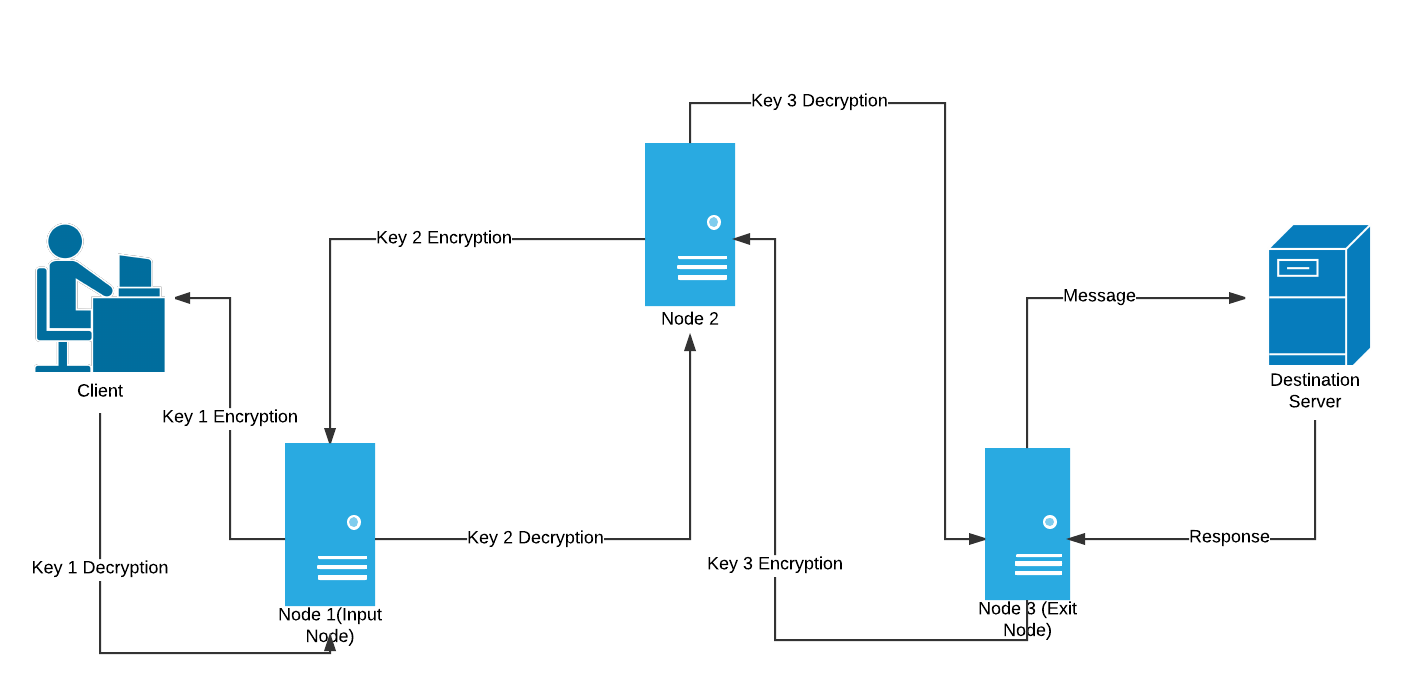
Onion Routing Circuit(made using lucidchart)
  1. The client with access to all the encryption keys i.e key 1, key 2 & key 3 encrypts the message(get request) thrice wrapping it under 3 layers like an onion which have to be peeled one at a time.
  2. This triple encrypted message is then sent to the first server i.e. Node 1(Input Node).
  3. Node 1 only has the address of Node 2 and Key 1. So it decrypts the message using Key 1and realises that it doesn’t make any sense since it still has 2 layers of encryption so it passes it on to Node 2
  4. Node 2 has Key 2 and the addresses of the input & exit nodes. So it decrypts the message using Key 2 realises that its still encrypted and passes it onto the exit node
  5. Node 3 (exit node) peels of the last layer of encryption and finds a GET request for youtube.com and passes it onto the destination server
  6. The server processes the request and serves up the desired webpage as a response.
  7. The response passes through the same nodes in the reverse direction where each node puts on a layer of encryption using their specific key
  8. It finally reaches the client in the form of a triple encrypted response which can be decrypted since the client has access to all the keys
How does it provide anonymity?
Imagine if there is sniffer listening in at the first connection(client – input node) all it can know is the address of the input node and a thrice encrypted message that doesn’t make sense. So all the attacker/sniffer knows that you are browsing tor.
Similarly if sniffing starts at the exit node all the sniffer sees is a server contacting another server but it can’t track the client or the source of the request generated.
But now you may think that if someone is listening in at Node 2 the will know the address of the input and exit and can trace the client and the destination server. But its not that simple, each of these nodes have hundreds of concurrent connections going on and to know that which one leads to the right source and destination is not that easy. In our circuit, the Node 2 is a middle node but it can be a part of another circuit on a different connection where it acts as the input node receiving requests or an exit node serving up webpages from various servers.
Vulnerability in Onion Routing
The only security flaw in onion routing is that if someone is listening in on a server at the same time and the matches the request at the destination to a request made by a client on the other side of a network by analyzing the length and the frequency of the characters found in the intercepted request or response at the destination server and using that to match with a same request made by a client a fraction of a second (time-stamps on requests and responses can also be helpful in deducing that) and then tracking them down and knowing their online activity and shattering the idea of anonymity. This is pretty hard to do but not impossible. But removing this flaw from Tor is virtually impossible.

Network goals

                 Computer Network means an interconnection of autonomous (stand alone) computers for information exchange. The connecting media could be a copper wire, optical fibre, microwave or satellite.
Networking Elements – The computer network includes the following networking elements:
  1. At least two computers
  2. Transmission medium either wired or wireless
  3. Protocols or rules that govern the communication
  4. Network software such as Network Operating System
Network Criteria:
The criteria that have to be met by a computer network are:
1. Performance – It is measured in terms of transit time and response time.
  • Transit time is the time for a message to travel from one device to another
  • Response time is the elapsed time between an inquiry and a response.
Performance is dependent on the following factors:
  • The number of users
  • Type of transmission medium
  • Capability of connected network
  • Efficiency of software
2. Reliability – It is measured in terms of
  • Frequency of failure
  • Recovery from failures
  • Robustness during catastrophe
3. Security – It means protecting data from unauthorized access.

Goals of Computer Networks: The following are some important goals of computer networks:
  1. Resource Sharing –
    Many organization have a substantial number of computers in operations, while are located apart. Ex. A group of office workers can share a common printer, fax, modem, scanner etc.
  2. High Reliability –
    If there are alternate sources of supply, all files could be replicated on two or, machines. I f one of them is not available, due to hardware failure, the other copies could be used.
  3. Inter-process Communication –
    Network users, located geographically apart, may converse in an interactive session through the network. In order to permit this, the network must provide almost error free communications.
  4. Flexible access –
    Files can be accessed from any computer in the network. The project can be begun on one computer and finished on another.

    Other goals are Distribution of processing functions, Centralized management and allocation of network resources, Compatibility of dissimilar equipment and software, Good network performance, Saving money, Scalability, Saving money, Access to remote information, Person to person communication etc.,

TCP Connection Termination

             In  TCP 3-way Handshake Process  we studied that how connection establish between client and server in Transmission Control P...