Thursday, July 12, 2018

Why does DNS use UDP and not TCP?

        DNS is an application layer protocol. All application layer protocols use one of the two transport layer protocols, UDP and TCP. TCP is reliable and UDP is not reliable. DNS is supposed to be reliable, but it uses UDP, why?

            There are following interesting facts about TCP and UDP on transport layer that justify the above.
1) UDP is much faster. TCP is slow as it requires 3 way handshake. The load on DNS servers is       also an important factor. DNS servers (since they use UDP) don’t have keep connections.
2) DNS requests are generally very small and fit well within UDP segments.
2) UDP is not reliable, but reliability can added on application layer. An application can use UDP      and can be reliable by using timeout and resend at application layer.

Transmission Modes in Computer Networks (Simplex, Half-Duplex and Full-Duplex)

               Transmission mode means transferring of data between two devices. It is also known as communication mode. Buses and networks are designed to allow communication to occur between individual devices that are interconnected. There are three types of transmission mode:-
  • Simplex Mode
  • Half-Duplex Mode
  • Full-Duplex Mode


  • Simplex Mode
    In Simplex mode, the communication is unidirectional, as on a one-way street. Only one of the two devices on a link can transmit, the other can only receive. The simplex mode can use the entire capacity of the channel to send data in one direction.
    Example: Keyboard and traditional monitors. The keyboard can only introduce input, the monitor can only give the output.


    Half-Duplex Mode
    In half-duplex mode, each station can both transmit and receive, but not at the same time. When one device is sending, the other can only receive, and vice versa. The half-duplex mode is used in cases where there is no need for communication in both direction at the same time. The entire capacity of the channel can be utilized for each direction.
    Example: Walkie- talkie in which message is sent one at a time and messages are sent in both the directions.


    Full-Duplex Mode
    In full-duplex mode, both stations can transmit and receive simultaneously. In full_duplex mode, signals going in one direction share the capacity of the link with signals going in other direction, this sharing can occur in two ways:
  • Either the link must contain two physically separate transmission paths, one for sending and other for receiving.
  • Or the capacity is divided between signals travelling in both directions.
  • Full-duplex mode is used when communication in both direction is required all the time. The capacity of the channel, however must be divided between the two directions.
    Example: Telephone Network in which there is communication between two persons by a telephone line, through which both can talk and listen at the same time.

    Network Devices (Hub, Repeater, Bridge, Switch, Router, Gateways and Brouter)

    1. Repeater – A repeater operates at the physical layer. Its job is to regenerate the signal over the same network before the signal becomes too weak or corrupted so as to extend the length to which the signal can be transmitted over the same network. An important point to be noted about repeaters is that they do not amplify the signal. When the signal becomes weak, they copy the signal bit by bit and regenerate it at the original strength. It is a 2 port device.

    2. Hub –  A hub is basically a multiport repeater. A hub connects multiple wires coming from different branches, for example, the connector in star topology which connects different stations. Hubs cannot filter data, so data packets are sent to all connected devices.  In other words, collision domain of all hosts connected through Hub remains one.  Also, they do not have intelligence to find out best path for data packets which leads to inefficiencies and wastage.
    Types of Hub
    • Active Hub :- These are the hubs which have their own power supply and can clean , boost and relay the signal along the network. It serves both as a repeater as well as wiring center. These are used to extend maximum distance between nodes.
    • Passive Hub :- These are the hubs which collect wiring from nodes and power supply from active hub. These hubs relay signals onto the network without cleaning and boosting them and can’t be used to extend distance between nodes.

    3. Bridge – A bridge operates at data link layer. A bridge is a repeater, with add on functionality of filtering content by reading the MAC addresses of source and destination. It is also used for interconnecting two LANs working on the same protocol. It has a single input and single output port, thus making it a 2 port device.
    Types of Bridges
    • Transparent Bridges :- These are the bridge in which the stations are completely unaware of the
      bridge’s existence i.e. whether or not a bridge is added or deleted from the network , reconfiguration of
      the stations is unnecessary. These bridges makes use of two processes i.e. bridge forwarding and bridge learning.
    • Source Routing Bridges :- In these bridges, routing operation is performed by source station and the frame specifies which route to follow. The hot can discover frame by sending a specical frame called discovery frame, which spreads through the entire network using all possible paths to destination.

    4. Switch – A switch is a multi port bridge with a buffer and a design that can boost its efficiency(large number of  ports imply less traffic) and performance. Switch is data link layer device. Switch can perform error checking before forwarding data, that makes it very efficient as it does not forward packets that have errors and  forward good packets selectively to correct port only.  In other words, switch divides collision domain of hosts, but broadcast domain remains same.
     
    5. Routers – A router is a device like a switch that routes data packets based on their IP addresses. Router is mainly a Network Layer device. Routers normally connect LANs and WANs together and have a dynamically updating routing table based on which they make decisions on routing the data packets. Router divide broadcast domains of hosts connected through it.
    img1

    6. Gateway – A gateway, as the name suggests, is a passage to connect two networks together that may work upon different networking models. They basically works as the messenger agents that take data from one system, interpret it, and transfer it to another system. Gateways are also called protocol converters and can operate at any network layer. Gateways are generally more complex than switch or router.

    7. Brouter – It is also known as bridging router is a device which combines features of both bridge and router. It can work either at data link layer or at network layer. Working as router, it is capable of routing packets across networks and working as bridge, it is capable of filtering local area network traffic.

    Basics of Computer Networking

    Open system:
    A system which is connected to the network and is ready for communication.
    Closed system:
    A system which is not connected to the network and can’t be communicated with.
    Computer Network: 
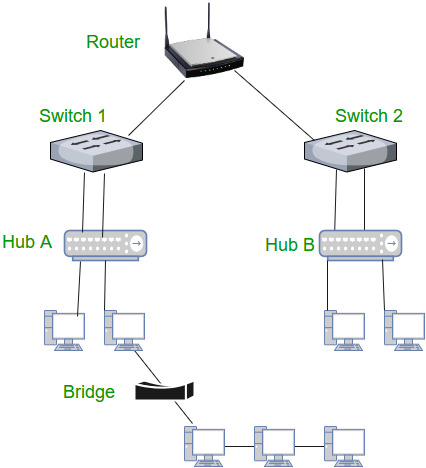
    It is the interconnection of multiple devices, generally termed as Hosts connected using multiple paths for the purpose of sending/receiving data or media.
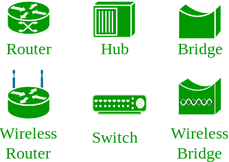
    There are also multiple devices or mediums which helps in the communication between two different devices which are known as Network devices. Ex: Router, Switch, Hub, Bridge.
    Computer-Networking-Diagram


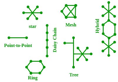
    The layout pattern using which devices are interconnected is called as network topology. Such as Bus, Star, Mesh, Ring, Daisy chain.
    Network-Topology-Diagram
    OSI:
    OSI stands for Open Systems Interconnection. It is a reference model that specifies standards for communications protocols and also the functionalities of each layer.
    Protocol: 
    Protocol is the set of rules or algorthims which define the way how two entities can communicate across the network and there exists different protocol defined at each layer of OSI model. Few of such protocols are TCP, IP, UDP, ARP, DHCP, FTP and so on.
    UNIQUE IDENTIFIERS OF NETWORK
    Host name:
    Each device in the network is associated with a unique device name known as Hostname.
    Type “hostname” in the command prompt and press ‘Enter’, this displays the hostname of your machine.


    IP Address (Internet Protocol address):
    Also know as Logical Address, is the network address of the system across the network.
    To identify each device in the world-wide web, Internet Assigned Numbers Authority (IANA) assigns IPV4 (Version 4) address as unique identifier for each device on the Internet.
    Length of the IP address is : 32-bits. (Hence we have 232 ip addresses available.)
    Type “ipconfig” in the command prompt and press ‘Enter’, this gives us the IP address of the device.
    MAC Address (Media Access Control address): 
    Also known as physical address, is the unique identifier of each host and is associated with the NIC (Network Interface Card).
    MAC address is assigned to the NIC at the time of manufacturing.
    Length of the MAC address is : 12-digit/ 6 bytes/ 48 bits
    Type “ipconfig/all” in the command prompt and press ‘Enter’, this gives us the MAC address.
    Port: 
    Port can be referred as logical channel through which data can be sent/received to an application. Any host may have multiple applications running, and each of this application is identified using the port number on which they are running on.
    Port number is a 16-bit integer, hence we have 216 ports available which are categorized as shown below:
    PORT TYPESRANGE
    Well known Ports0 – 1023
    Registered Ports1024 – 49151
    Ephemeral Ports49152 – 65535
    Number of ports: 65,536
    Range: 0 – 65535
    Type “netstat -a” in the command prompt and press ‘Enter’, this lists all the ports being used.
    Socket:
    The unique combination of IP address and Port number together are termed as Socket.
    Few more concepts
    DNS Server:
    DNS stands for Domain Name system.
    DNS is basically a server which translate web addresses or URL (ex: www.google.com) into their corresponding IP addresses. We don’t have to remember all the IP addresses of each and every website.
    The command ‘nslookup’ gives you the IP address of the domain you are looking for. This also provides the information of our DNS Server.
    ARP:
    ARP stands for Address Resolution Protocol.
    It is used to convert the IP address to its corresponding Physical Address(i.e.MAC Address).
    ARP is used by the Data Link Layer to identify the MAC address of the Receiver’s machine.
    RARP:
    RARP stands for Reverse Address Resolution Protocol.
    As the name suggest, it provides the IP address of the a device given physical address as input. But RARP has become obsolete since the time DHCP has come into picture.

    Circuit Switching VS Packet Switching

    CIRCUIT SWITCHINGPACKET SWITCHING
    In circuit switching there are 3 phases
    i) Connection Establishment.
    ii) Data Transfer.
    iii) Connection Released.
    In Packet switching directly data transfer takes place .
    In circuit switching, each data unit know the entire path address which is provided by the sourceIn Packet switching, each data unit just know the final destination address intermediate path is decided by the routers.
    In Circuit switching, data is processed at source system onlyIn Packet switching, data is processed at all intermediate node including source system.
    Delay between data units in circuit switching is uniform.Delay between data units in packet switching is not uniform.
    Resource reservation is the feature of circuit switching because path is fixed for data transmission.There is no resource reservation because bandwidth is shared among users.
    Circuit switching is more reliable.Packet switching is less reliable.
    Wastage of resources are more in Circuit SwitchingLess wastage of resources as compared to Circuit Switching

    IPv6

                  IP v6 was developed by Internet Engineering Task Force (IETF) to deal with the problem of IP v4 exhaustion. IP v6 is 128-bits address having an address space of 2^128, which is way bigger than IPv4. In IPv6 we use Colon-Hexa representation. There are 8 groups and each group represents 2 Bytes.
    In IPv6 representation, we have three addressing methods :


  • Unicast
  • Multicast
  • Anycast

  • Unicast Address: Unicast Address identifies a single network interface. A packet sent to unicast address is delivered to the interface identified by that address.
    Multicast Address: Multicast Address is used by multiple hosts, called as Group, acquires a multicast destination address. These hosts need not be geographically together. If any packet is sent to this multicast address, it will be distributed to all interfaces corresponding to that multicast address.
    Anycast Address: Anycast Address is assigned to a group of interfaces. Any packet sent to anycast address will be delivered to only one member interface (mostly nearest host possible).
    Note : Broadcast is not defined in IPv6.
    Types of IPv6 address:
    We have 128 bits in IPv6 address but by looking at first few bits we can identify what type of address it is.
    PREFIXALLOCATIONFRACTION OF ADDRESS SPACE
    0000 0000Reserved1/256
    0000 0001Unassigned (UA)1/256
    0000 001Reserved for NSAP1/128
    0000 01UA1/64
    0000 1UA1/32
    0001UA1/16
    001Global Unicast1/8
    010UA1/8
    011UA1/8
    100UA1/8
    101UA1/8
    110UA1/8
    1110UA1/16
    1111 0UA1/32
    1111 10UA1/64
    1111 110UA1/128
    1111 1110 0UA1/512
    1111 1110 10Link-Local Unicast Addresses1/1024
    1111 1110 11Site-Local Unicast Addresses1/1024
    1111 1111Multicast Address1/256
    Note : In IPv6, all 0’s and all 1’s can be assigned to any host, there is not any restriction like IPv4.
    Provider based Unicast address :
    These are used for global communication.
    First 3 bits identifies it as of this type.
    Registry Id (5-bits) : Registry Id identifies the region to which it belongs. Out of 32 (i.e. 2^5), only 4 registry id’s are being used.

    Provider Id : Depending on the number of service providers that operates under a region, certain bits will be allocated to Provider Id field. This field need not be fixed. Let’s say if Provider Id = 10 bits then Subscriber Id will be 56 – 10 = 46 bits.
    Subscriber Id : After Provider Id is fixed, remaining part can be used by ISP as normal IP address.
    Intra Subscriber : This part can be modified as per need of organization that is using the service.
    Geography based Unicast address :
    Global routing prefix : Global routing prefix contains all the details of Latitude and Longitude. As of now, it is not being used. In Geography based Unicast address routing will be based on location.
    Interface Id : In IPv6, instead of using Host Id, we use the term Interface Id.
    Some special addresses:
    Unspecified – 
    Loopback –
    IPv4 Compatible –
    IPv4 mapped –
    Local Unicast Addresses :
    There are two types of Local Unicast addresses defined- Link local and Site Local.
    Link local address:
    Link local address is used for addressing on a single link. It can also be used to communicate with nodes on the same link. Link local address always begins with 1111111010 (i.e. FE80). Router will not forward any packet with Link local address.
    Site local address:
    Site local addresses are equivalent to private IP address in IPv4. Likely, some address space is reserved, which can only be routed within an organization. First 10-bits are set to 1111111011, which is why Site local addresses always begin with FEC0. Following 32 bits are Subnet ID, which can be used to create subnet within organization. Node address is used to uniquely identify the link; therefore, we use 48-bits MAC address here.

    Routing v/s Routed Protocols

               The Network Layer of the OSI Model is responsible for providing logical addressing, which routers use to select best path for routing packets. There are two types of packets used at this layer :
    1. Data Packets –
      The user data is transferred in the inter-network by these data packets. Routed protocolsare those protocols which support such data traffic. Examples of routed protocols are IPv4, IPv6 and AppleTalk.
    2. Route Update Packets –
      The information about the networks connected to all the routers is updated to the neighbouring routers through route update packets. Routing protocols are the ones that are responsible for sending them. Examples of routing protocols are RIP(Routing Information Protocol), EIGRP(Enhanced Interior Gateway Routing Protocol) and OSPF(Open Shortest Path First).
    Now let’s take an real-life analogy to better understand the difference between routed and routing protocols.
    Suppose you want to go to your home after your semester examinations. You book a cab or take a bus to your home. In the path of your journey, you encounter several sign boards which help you take proper or best path, or in case of a cab, Google Maps will help you in choosing the best route.
    In this analogy, consider yourself as the DATA, the bus or cab as the ROUTED PROTOCOL and the sign boards or the GPS installed in your driver’s phone as the ROUTING PROTOCOL.
    Similarly, in a network routers use routing protocols to determine the best path for a packet to travel through the inter-network more efficiently. Routed protocols are assigned to an interface and determine the method of delivering the packet.
    Now, lets move on to the different types of routing protocols.


    Abbreviations –
    IGP – Interior Gateway Protocol
    EGP – Exterior Gateway Protocol
    RIP – Routing Information Protocol
    IGRP – Interior Gateway Routing Protocol
    OSPF – Open Shortest Path First
    ISIS – Intermediate System to Intermediate System
    EIGRP – Enhanced Interior Gateway Routing Protocol
    BGP – Border Gateway Protocol

    TCP Connection Termination

                 In  TCP 3-way Handshake Process  we studied that how connection establish between client and server in Transmission Control P...